Waves, Phasors, and Signals — The Math of Interference and Diffraction
1. Introduction
Have you ever wondered why noise-canceling headphones work? Or how a tiny hologram can contain a 3D image? Or even just why you see shimmering rainbow patterns on a soap bubble?
The answer to all of these is wave interference and diffraction. These are fundamental concepts in physics, but today I want to look at them through a different lens: the lens of signal processing. It turns out that the propagation of a wave is one of the most elegant and powerful signal processing systems in the universe.
2. The Wave as a Complex Signal
In signal processing and physics, we describe a simple wave using complex exponentials, thanks to Euler’s formula: .
We can represent a wave at a position and time as:
Let’s break this down:
- is the amplitude (the wave’s “strength”).
- is the phasor. This is the magic part. It’s a vector on the complex plane (a “clock hand”) that rotates.
- is the angular frequency (how fast it oscillates in time).
- is the wave vector (its direction of travel and spatial frequency, where ).
- is the initial phase.
For the rest of this post, we’ll mostly ignore the time part () since it’s common to all waves from the same source. We’ll just focus on the complex amplitude (the spatial part):
Think of this as a single complex number for every point in space. Its magnitude is the amplitude, and its angle is its phase.
Propagation is just a phase shift. As a wave travels from a source at to a point , it covers a distance . This journey “rotates” the phasor. The wave at is:
(The shows the amplitude decaying with distance , and ).
The key takeaway: Propagation = Phase Rotation.
3. Interference: The Superposition Problem
Interference is the simplest case. It’s just what happens when two or more waves meet at the same point. The math is simple: you just add them. This is the Principle of Superposition.
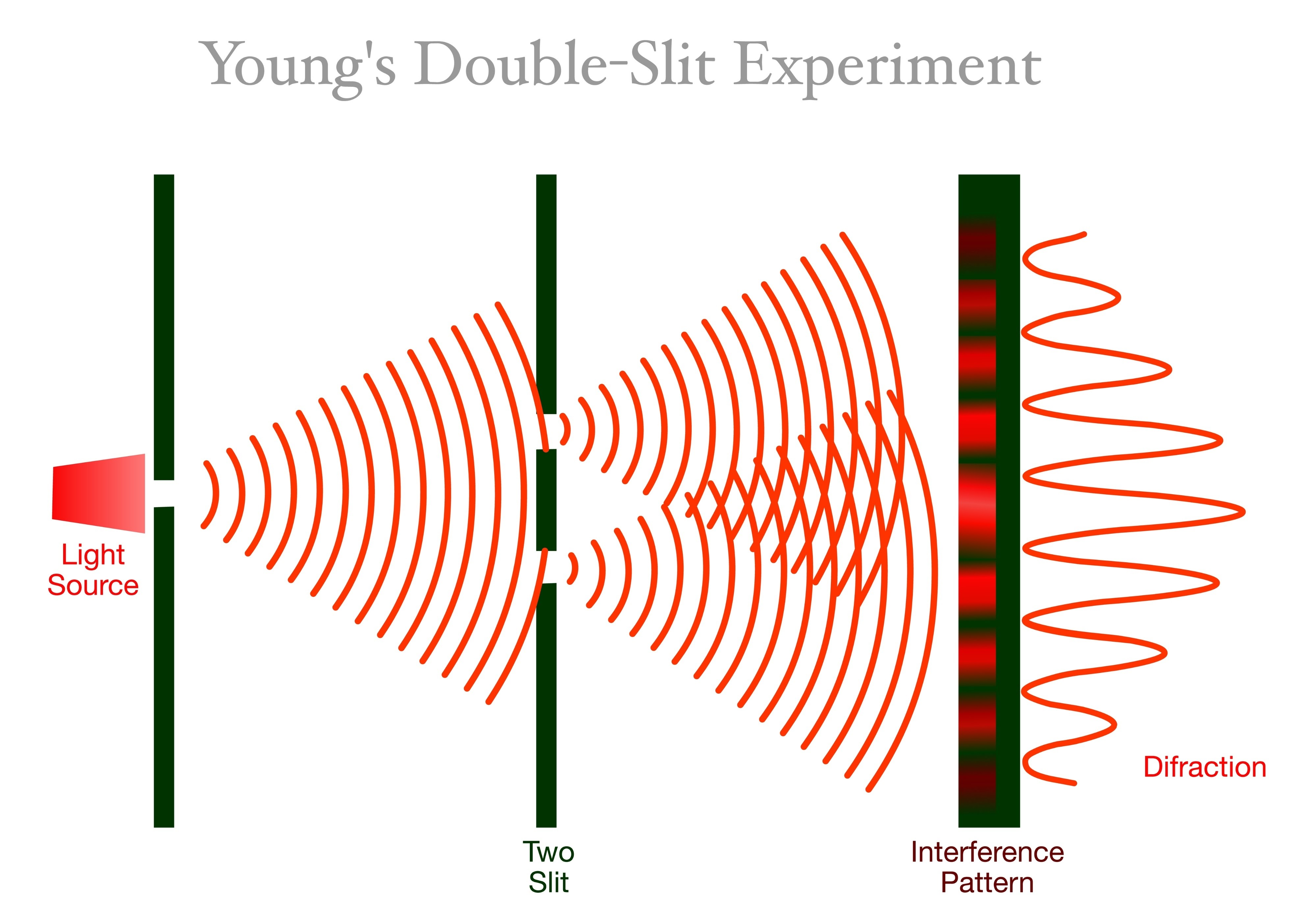
Let’s model the classic double-slit experiment. We have two tiny sources (slits) at and . We want to know the total wave at an observation point on a screen.
- Wave 1 (from slit 1): Propagates a distance .
- Wave 2 (from slit 2): Propagates a distance .
(We’ll assume for simplicity, as the distances are similar).
The total wave at is the sum of these two complex numbers:
What we actually see (the brightness or intensity) is the magnitude squared of this complex number, .
So, this simplifies to:
The intensity depends on the cosine of the difference in path lengths ().
- If the path difference is a whole number of wavelengths (), the phases align (), the waves add up, and we get a bright spot (constructive interference).
- If the path difference is a half-wavelength (), the phases are opposite (), the waves cancel out, and we get a dark spot (destructive interference).
If we assume the slits are separated by a distance and the screen is far away at distance , we can approximate the path difference as:
where is the position on the screen. Plugging this in, we get the classic interference pattern:
Interference is nothing more than the addition of complex phasors, where their relative angles are set by the propagation delay (path length difference).
4. Diffraction: Interference on a Grand Scale
Diffraction is interference from a continuous number of sources.
Instead of two discrete slits, imagine a single wide aperture (like a single slit, a circular hole, or any shape). The Huygens-Fresnel Principle states that every single point inside that aperture acts as a new source of waves.
To find the wave at a point on our screen, we can’t just add two waves. We have to integrate (sum up) the contributions from every point in the aperture.
Let the aperture’s transmission be described by an “input signal” (e.g., inside the slit, outside). The propagation from to on a screen at distance introduces a distance .
The total wave at the screen is as follows:
This integral is the heart of wave propagation. In signal processing terms:
- is the input signal.
- is the output signal.
- is the system’s impulse response (or propagator).
The propagation of the wave is a linear system that “processes” the aperture function.
5. The Big Reveal: Propagation is the Fourier Transform
If we make a very common approximation—that the screen is far away (the Fraunhofer approximation)—the math simplifies beautifully.
In this far-field limit, the distance in the phase term can be approximated as:
Plugging this into our integral and dropping some constant phase/amplitude factors (which just dim or shift the whole pattern), we get:
We can define new spatial frequency coordinates:
Substituting these in, our diffraction pattern as a function of these new coordinates is:
This is the 2D Fourier Transform.
This is a profound result:
The wave pattern you see from a far-away aperture (diffraction) is the Fourier Transform of the aperture’s shape.
- A wide single slit ( is a
rectfunction) produces asincfunction pattern (). - A tiny circular hole ( is a
circfunction) produces an Airy disk (a Bessel function), which is why stars look like blurry spots, not perfect points, in a telescope. - A double slit (two
rectfunctions) produces the classic interference fringes modulated by asincenvelope.
The resulting diffraction pattern is:
5.1. What it all means:
- Propagation = Signal Processing: Wave propagation acts like a physical computer that calculates the Fourier Transform.
- Interference: This is just the linear addition of complex signals.
- Diffraction: This is the result of a “propagation filter” being applied to an “input aperture signal,” which, in the far-field, is the Fourier Transform.
This math is why signal processing techniques are not just for audio and images, but are fundamental to describing reality itself. The next time you see sunlight filter through a narrow gap, you’re not just seeing light—you’re seeing a Fourier Transform computed by nature.
Physics, Signal Processing, Waves — Oct. 21, 2025
Unless otherwise stated, all content on this blog is licensed under CC BY-NC-SA 4.0 |
RSS subscribe |
Friends
鄂ICP备2025091178号 |
对应的中文页面尚未上线