The Magic of Holography — from a Signal Processing Perspective
1. Introduction
Holography is a fascinating technique that allows us to record and reconstruct three-dimensional world using coherent light sources, such as lasers. The original concept of holography was introduced by Dennis Gabor in 1948, honoring him the Nobel Prize in Physics in 1971. In this article, we will explore the principles of holography from a signal processing perspective, shedding light on how holograms are created and reconstructed.
This article is a review and summary of a lecture by Prof. Hua Lee from UCSB. The lecture is part of the course Imaging Systems (ECE 278C).
To have visual intuition, I highly recommend watching this video.
2. Mathematical Notations of Holography
The difference between photography and holography lies in the way light information is recorded. For photography, we typically record the intensity of light reflected from an object onto a 2D surface, such as a photographic film or a digital sensor. However, holography goes beyond this by capturing both the amplitude and phase information of the light waves.
There are three main objects in holography: the 3D-object wave, the reference wave, and the film where the hologram is recorded. We denote
- the 3D-object wave as
- the reference wave as
and represent the amplitudes of the object wave and reference wave respectively, is the phase distribution of the object wave, and is the spatial frequency of the reference wave.
3. Recording the Hologram
The recording setup of holography is shown below:
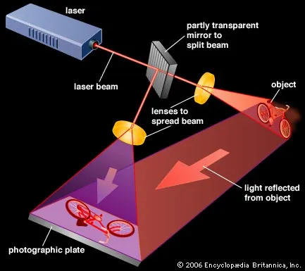
As shown in the figure, the laser beam is split into two parts: one part illuminates the object, creating the object wave, while the other part serves as the reference wave. Both waves interfere on the photographic film, creating an interference pattern that encodes the amplitude and phase information of the object wave.
The intensity of the combined waves on the film can be expressed as:
After the chemical processing of the photographic film, the hologram is formed, which contains the recorded intensity pattern. Normally, we use a linear film:
where is a constant related to the film’s sensitivity.
4. Reconstructing the Hologram
To reconstruct the hologram, we illuminate the recorded hologram with the exact same reference wave called reconstruction wave, the transmitted wave through the hologram can be expressed as a simple multiplication of (2) and the reference wave:
The transmitted wave consists of three parts:
- Part 1 Copy of the reference wave: modulated by the object intensity and reference intensity, directly passing through the hologram. We usually ignore this part during reconstruction as it does not contribute to the image formation.
- Part 2 Copy of the object wave: the wave that we see as the virtual image of the object. This is the main component we are interested in.
- Part 3 Conjugation of the object wave: the wave that forms a conjugate image, which can be seen in front of the hologram plane if putting a screen there.
The first two parts are easy to imagine. While the third part, the conjugate wave, is a bit tricky. For now, we can simply understand that it is a phase-conjugated version of the object wave, we will explore it further in the next section.
5. The Signal Processing Perspective
From a signal processing perspective, holography can be viewed as a method of encoding and decoding spatial frequency information of light waves. The interference pattern recorded on the hologram contains a wealth of information about the spatial frequencies of the object wave. When we illuminate the hologram with the reference wave, we effectively perform a correlation operation that retrieves the original object wave’s phase and amplitude information which was never recorded through photography techniques.
What really amazes me is that the extreme complex interference between the reference and object waves on the hologram can be mathematically modeled as simple multiplication and addition operations, similar to how signals are modulated and demodulated in communication systems.
In a communication system, a high-frequency carrier wave is modulated by a low-frequency information signal to transmit data over long distances. At the receiver end, the carrier wave is used to demodulate the received signal, retrieving the original information. A typical amplitude modulation (AM) can be expressed as:
where is the transmitted signal, is the message signal, and is the carrier wave.
What happens in holography is quite similar. The reference wave acts as the carrier wave, while the object wave serves as the message signal. In this way, when we record the intensity of the combined waves on the hologram, we are effectively modulating the reference wave with the object wave’s information. During reconstruction, illuminating the hologram with the reference wave demodulates the recorded signal, retrieving the original object wave’s phase and amplitude information.
6. The Philosophical Insight
When we look at holography from a signal processing perspective, we can draw a profound philosophical insight about the nature of information and reality. Holography teaches us that the information about a three-dimensional object can be fully encoded in a two-dimensional surface, and that this information can be perfectly reconstructed under the right conditions.
We human beings often perceive reality through our limited senses. Our eyes, ears, and skin capture only the intensity of light, sound, and touch, respectively. However, most of the information about the world around us is encoded in the phase of the waves that reach our senses.
Holography reminds us that there is more to reality than what meets the eye, and that by understanding the underlying signals, we can unlock deeper insights into the nature of existence.
Holography, Imaging, Signal Processing — Oct. 20, 2025
Unless otherwise stated, all content on this blog is licensed under CC BY-NC-SA 4.0 |
RSS subscribe |
Friends
鄂ICP备2025091178号 |
对应的中文页面尚未上线